
Many plastic parts contain specialised features such as snap hooks, mounting bosses and a gap at the joint where two components come together. Let see how we can do this inside SOLIDWORKS. There's a handy set of tools located in the menu, Insert > Fastening Features.


The model is first split into multiple bodies to identify the
upper and lower housing. The shell tool can be used to hollow out the part.
It will leave the faces you select open and create thin-walled features on the
remaining faces.
We will use the Lip/Groove
feature to create an edge. It is often used in plastic parts to prevent an
edge-to-edge joint between two parts.
Select the Lip/Groove
feature. Highlight the upper housing to receive the groove and the lower
housing to receive the lip.
For the Groove
Selection select the face and the edge you wish to apply. Repeat the same
procedure for the Lip Selection. You
can then define dimensions in the parameters.

Snap Hooks are common features in plastic parts enabling
quick assembly without the need for tools or fasteners.
First create sketch points where you wish locate the snap
hooks. Select Snap Hook feature,
pick the sketch point. Select a reference plane to define the vertical
direction of the snap hook. Select another reference plane to define the direction
of the hook (use Reverse direction if the hook is pointed the wrong way).
Define the dimensions in the Snap Hook
Data. Repeat the same procedure for each snap hook.


Next is to create the Snap Hook Groove. The dimensions of
the snap hook groove are driven by the snap hook. You can change the offsets
or clearances through the PropertyManager. Again, repeat the procedure for the
other snap hook.


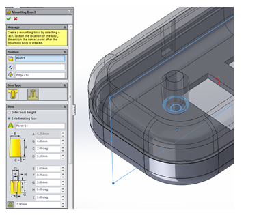
Mounting boss can be added for hardware fasteners. When
you create a mounting boss it can either be a through clearance hole for the
fastener or one with a blind hole for the threads.
First we will create the through clearance hole boss as
shown below. You can reposition the mounting boss by editing the 3D sketch.

Now that we have a clearance hole boss, it will be easier to
create the corresponding blind pilot hole boss because we can reference some of
the existing geometry to orient the boss and define its height.
To define the height, select the
mating face option and select the planar face on the mounting boss of the lower
housing.
For added support you can set the fin parameters. A reference plane can be used to orientate the fins. The number of fins will be equally spaced out.


No comments:
Post a Comment